Management Issues in Flex PCB Fabrication
A flexible printed circuit board (PCB) is an essential component in electronic products. Often, it must endure harsh conditions like high humidity or extreme temperatures for years. This is why the choice of a base material that can withstand these environmental stresses is crucial for flex pcb fabrication. Many manufacturers use a copper-clad laminate (CCL) that’s made of polyimide films, allowing the boards to bend and fold with little to no damage. A CCL can also prevent thermal cycling stress, which is a problem that occurs when repeated heat changes cause the substrate to expand and pull on copper conductors.
A key factor that contributes to the longevity of a flex PCB is its ability to disperse heat. It’s important for a flex PCB to remain within the glass transition temperature, which is the point at which the substrate becomes rubbery and no longer maintains its mechanical integrity. If the flex circuit is exposed to temperatures above this point, it will experience delamination and short circuits.
To avoid this, a flex PCB must be manufactured with the proper materials and the right layer stackup. This is especially important if you’re using a flex circuit in a dynamic application that requires a high degree of flexibility. The optimum copper layer count for a flex PCB depends on the product’s design, production speeds and solder mask requirements. For example, if your design requires a maximum of two layers for a flexible section, you may want to add an additional rigid layer.

Thermal Management Issues in Flex PCB Fabrication
In addition to layer stackup, the etching process and copper plating are crucial for flex PCB fabrication. During the etching process, photosensitive etch resist is coated over the film surface and then exposed to UV light. Once the exposed copper is etched, the etch resist is chemically stripped away from the remaining traces. The etching step also involves plating through-holes with copper. This is necessary to ensure the stability of the components, as well as to provide a strong foundation for mounting.
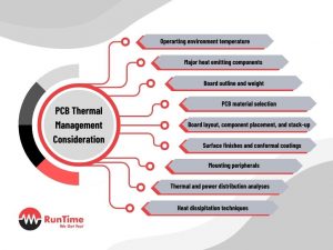
It’s also important to keep in mind that the flex PCB’s component density and power amplification will determine its heat production. Therefore, it’s best to place the most sensitive and heat-producing components near each other, while avoiding placing them in groups that create hot spots. Additionally, it’s a good idea to use wide copper traces and polygon fills for maximum thermal performance.
Finally, it’s a good idea to include cooling solutions like fans to facilitate airflow and carry the heat away from the component. By addressing these issues, you can help your flex circuit last longer and perform better in its final product.